How data is transmitted in LTE
Overview
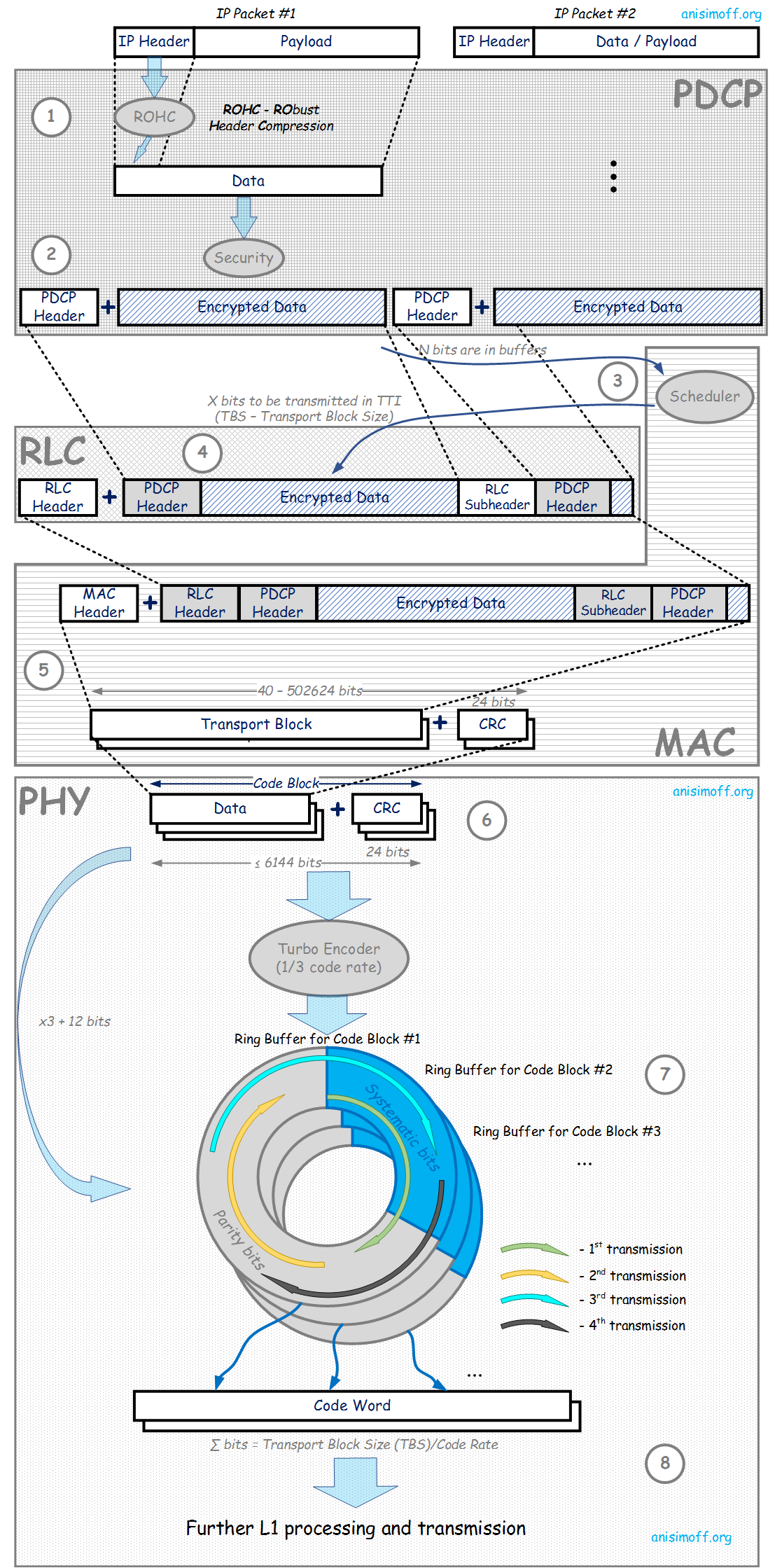
A picture below shows main stages that data packet passes in LTE base station (eNB) to be transmitted to mobile device (User Equipment, UE), i.e. data transmission is presented for Downlink (DL) direction. After the picture there is short description of each step.
Stages of Data Transmission in LTE
- LTE eNB operates with IP packets. It receives IP packets and passes them to PDCP (Packet Data Convergence Protocol). PDCP layer supports header compression and it's performed according to RObust Header Compression (ROHC) defined by RFC 4995. An idea is to reduce size of upper layers headers (not only IP) as it contains static information. Especially it's important in case of VoIP packets transmission because of headers can represent more than a half of packet.
- After ROHC PDCP performs data encryption to secure user data and then adds PDCP header. PDCP header size is between 1 and 3 bytes.
- There is Radio Resource Scheduler that is a part of MAC (Media Access Control) layer. It collects all information about how many data are in buffers to be transmitted to each active UE, actual information about radio link quality to each UE, whether there are any packets to be retransmitted, each UE status (actually whether UE is listening to or is in power saving mode with turned off receiver for some time), schedule for system information transmissions (e.g. synchronization signals, Master Information Block, System Information Blocks). And based on all of this information scheduler each TTI (Transmission Time Interval, TTI = 1 ms) distributes radio resources among active UE and sets transmission parameters for each transmission. Also scheduler defines how many data can be transmitted within a TTI for a given UE and it's called as Transport Block Size (TBS) and set in bits.
- Once amount of data to be transmitted is known RLC (Radio Link Control) layer forms a packet (called as RLC PDU - RLC Packet Data Unit). This packet includes encrypted user data, PDCP header(s) and RLC header(s). Depending on allocation size for a given UE, RLC PDU can include a part of PDCP packet, a whole PDU packet or several PDU packets (as well as their parts). In case of packet segmentation and / or concatenation additional RLC subheader is added.
- After RLC, a packet goes to MAC layer where MAC header is added. Then the packet is divided into Transport Blocks based on TBS set by the scheduler. TBS depends on allocation size and MCS (Modulation and Coding Scheme). See more about Transport Block Size, MCS and LTE throughput calculation. Number of transport blocks is also defined by the scheduler and can be 1 or 2. Also CRC block is added to each transport block to distinguish between successful and unsuccessful data transmission on receiver side. CRC size is 24 bits.
- Then transport block is passed to Physical Layer where it's divided into Code Blocks. Each Code Block has its CRC (unless Transport Block size ≤ maximum Code Block size. In this case Transport Block CRC is used).
- Each Code Block is passed to Turbo encoder. Code rate is 1/3, i.e. there are three times more data on encoder output comparing to input. On output there are Systematic bits (represent 1/3 of encoder output) and Parity bits (represent 2/3 of encoder output). Output is stored into a ring buffer. There are as many ring buffers as a number of Code Blocks. In general the whole ring buffer can be transmitted or just a part of it. It depends on effective code rate (i.e. number of user bits to overall allocation size ratio) set by scheduler for a particular transmission. If data transmission is unsuccessful there will be retransmission scheduled and another part of ring buffer will be transmitted.
- Data from ring buffers are concatenated into Code Words. Number of code words equals to a number of Transport Blocks and can be 1 or 2. Code word size equals to Transport Block Size divided by effective code rate. Then it's modulated (see more about code rate and modulation), mapped to MIMO layers and radio resources, goes though IFFT (Inverse Fast Fourier Transform) and transmitted to radio module for over the air transmission.
You can share your feedback, questions and/or proposals sending an email to alexey.anisimov86[at]gmail.com

